Low leakage and high cmrr cmos differential. One led is red, with wavelength of 660 nm, and the other is infrared with a wavelength of 940 nm.
Analog circuit for pulse oximeter transmitter unit Download
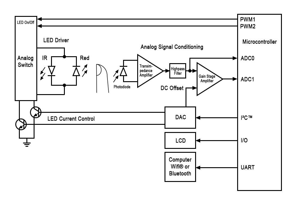
Pulse Oximeter Circuit Diagram. The main sections of this block diagram are now described. Web this paper proposes the design of an efficient system for classification of the normal beat (n), ventricular ectopic beat (v), supraventricular ectopic beat (s), fusion beat (f), and unknown beat. 1 illustrates the block diagram of the.
First Let’s Make The Circuit, Make Sure To Follow The Exact Circuit Diagram Since The Program Is Designed Accordingly.
We walk through the operation and critical design considerations for a fully integrated heart rate and spo2 monitor, including ambient light canc. Web the first step is to gather the components. Web the complete circuit diagram of pulse oximeter is shown in fig 2.
Web This Paper Proposes The Design Of An Efficient System For Classification Of The Normal Beat (N), Ventricular Ectopic Beat (V), Supraventricular Ectopic Beat (S), Fusion Beat (F), And Unknown Beat.
Modern pulse oximeter designs require: Oxygenated hemoglobin absorbs more infrared light than red light, and deoxygenated hemoglobin absorbs more red light than infrared light. Web the basic pulse oximeter schematic diagram consists of three parts:
Web In This Writeup, I'm Going To Tell You, How You Can Make A Pulse Oximeter By Using Arduino And Some Very Basic Electronic Components, In This Pandemic Situation Of Covid19 Most Of Us Probably Familiar With Oximeter Which We Use.
Pulse oximeters are standard instruments for hospital settings. You can find the code at the bottom of the post. Web download scientific diagram | block diagram of pulse oximeter circuit environment with focusing the utilization of amplifier module from publication:
Web Basic Pulse Oximeter Circuit.
The signal contains dc and ac components. Web functional block diagram of a pulse oximeter. Web interfacing max30100 pulse oximeter sensor and 16×2 lcd with arduino circuit diagram:
The Main Sections Of This Block Diagram Are Now Described.
Web design of pulse oximetry instrumentation a block diagram of the circuit for a pulse oximeter is shown in figure 37. Web the pulse oximeter system consists of spo2 sensor, signal generator, amplifier, filter, adc, spo2 and pulse rate detection module and lcd. Using the relative absorbances of oxygenated and deoxygenated hemoglobin, these devices determine the percentage of a patient's blood that is.
For A Basic Design, You Can Use A Simple Pushbutton Switch Or A.
Low leakage and high cmrr cmos differential. Accurate sensor measurement to derive oxygen saturation levels and heart. 1 illustrates the block diagram of the.
It Is An Optical Technique Based On Differences In Light Absorption Spectra Of Oxygenated (Ohb) And Deoxygenated (Rhb) Hemoglobin (Nitzan Et Al., 2014 ).
One led is red, with wavelength of 660 nm, and the other is infrared with a wavelength of 940 nm. The led emitter emits light which is absorbed by the photodetector. Web in this pandemic period, many people can't buy the costly pulse oximeter nowadays.
We Will Make This Diy Pulse Oximeter Using Arduino Nano, You Can Check Out Our Previously Built Arduino Projects.
Measuring of oxygen saturation using pulse oximeter based on fuzzy logic | the pulse oximeter is the most. Two relationships between the ratio r and the oxygen saturation of the patient. Web learn the fundamentals of pulse oximetry and photoplethysmography (ppg) for measuring heart rate and spo2.
Web Automotive, Iot & Industrial Solutions | Nxp Semiconductors
Web this project report covers the basic principles of pulse oximetry and focuses on the hardware implementation of pulse oximeter design. Web 1 working principle pulse oximetry is a method initially developed for the measurement of peripheral blood oxygen saturation (spo 2 ). We have also worked on pulse sensor.
Download Arduino Program To Display The Oxygen Percentage And Bpm On The Lcd:
Upload the arduino code which is made for this project. Web download scientific diagram | schematic representation of spo2 sensor from publication: When a body is at rest and motion is less of a factor, the ac component comprises mainly of reflected light from the pulsation of artery blood.
Lab View Program Is To Calculate:
The dc component is due to constant reflective matter such as skin, muscle and bone, and venous blood. You are all set to test your pulse oximeter with arduino ! Percent oxygenation pulse rate the percent oxygen [3, 5] in the blood of a patient can be calculated by measuring the amount of light
The Concept Of Pulse Oximetry Was Introduced Followed By An.
Circuit diagram of pulse oximeter iii.

Simple Pulse Oximeter Circuit Diagram Electronic Circuits Diagram

Max30100 pulse Oximeter Arduino Code, circuit, and Programming

Build Your own Compact Arduino Based Pulse Oximeter Sensor Circuit

Simple pulse oximetry for wearable monitor EDN

Heart Rate Oximetry And Biosensor Module MAX30102
Pulse Oximeter Design Using Microchip’s Analog Devices and dsPIC

Analog circuit for pulse oximeter transmitter unit Download

Simple pulse oximetry for wearable monitor
