The op amp circuit senses current The op amp circuit senses current
LED Running Light Circuit Engineering Projects
Running Light Circuit Diagram. V = i × r + vl= l (di/dt) with the above equation, it can be stated that vr is based on the current ‘i’, whereas vl is based on the rate of change in current. Web the led chaser circuit diagram | running light circuit project concept and construction is very easy, few key components are needed to build it. X l = 2πfl ohms.
Web The Led Chaser Circuit Diagram | Running Light Circuit Project Concept And Construction Is Very Easy, Few Key Components Are Needed To Build It.
Web running light led circuit diagram dual colour led chaser using not gate inverter 1 comment / led chaser flasher circuit / by admin colour changing led chaser circuit using bicolour led here i am presenting a circuit of 10 dual colour led flasher (not using flashing led) which blinks one by one in sequence. The key components are ne555 timer ic, potentiometer, resistor, capacitor, cd4017 counter ic, and leds. The voltage drop across inductor and resistor is given by.
It Means Same As A Pendulum It Travels Back And Forth.
It is one of the simplest analogue infinite. The op amp circuit senses current The rate at which this takes place is determined by using the clock at pin 14.
Led Light Sequencer Circuits Running Eleccircuit Com.
Even the lamps, transformers, welding devices operate at low lagging power factors. Web the working principle see in the circuit above. The design and working of this circuit are very simple and straightforward.
The Clock Is Generated By Ic1, Which Is Arranged As An Astable Multivibrator.
Web the running lights schematic diagram and printed circuit board (pcb) were developed in easy eda online environment. Web 3 interesting drl (day time running light) circuits for your car. Vr = i × r and vl= l (di/dt) so, the rl circuit formula is given by.
The Condenser Mic Converts Audio Signals Into Electric Signals.
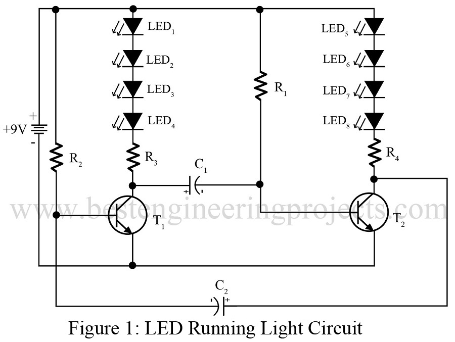
The rate at which this happens is determined by the clock at pin 14. Both of these transistors are configured in astable multivibrator mode. The entire circuit of led running light is designed using two general purpose npn transistors.
This Circuit Can Be Utilized For The Beautification Of The Car Or It Can Be Helpful At The Time Of Crisis When Your Car Broke Down And You Need Help.
Web knowing how to read and understand a running lights circuit diagram can help you get your vehicle in working order and on the road again with minimal hassle. Here we will configure the 555 timer ic as a frequency generator. From the value of x l and r, calculate the total impedance of the circuit which is given by.
Web Running Light Led Circuit Diagrams Provide A Great Way To Understand The Details Behind Led Lighting And To Create Custom Lighting Applications.
This diagram provides a visual breakdown of the wiring system that is connected to your car's electrical system and is an essential component in. Web since the value of frequency and inductor are known, so firstly calculate the value of inductive reactance x l: 1 shows the circuit for the audio controlled running light, while fig.
V = I × R + Vl= L (Di/Dt) With The Above Equation, It Can Be Stated That Vr Is Based On The Current ‘I’, Whereas Vl Is Based On The Rate Of Change In Current.
Circuit diagram of led knight rider circuit diagram: 2 shows the pin configuration of triac bt136. Cd4017 based led light 81 chaser full project.
How To Build A Simple.
Next each led, one at a timing light up, and replay back to first. Led chaser circuit using ic 4017 and 555. Drl or day time running lights are a chain of bright lights mostly leds installed just under a vehicle's headlight, which illuminate automatically during day time to ensure that others can distinctly notice the vehicle approaching even from a distance.
Transistor T1 Amplifies The Microphone Signals, Which Provide Clock Pulses To Decade Counter Ic Cd4017 (Ic1).
Decade scaler ic2 ensures that the leds mild sequentially. Web outline simple led running light circuit (flashing leds) circuit diagram components required working of the project led chaser circuit using cd4017 and 555 circuit diagram components required working of the project two way running leds with 11 leds, cd4017 and 555 timer ic circuit diagram components required. X l = 2πfl ohms.
Web With A Better Understanding Of The Circuit Diagram Of Led Running Lights, You’ll Be Able To Enjoy The Beauty Of These Lights For Many Years To Come.
Whether you’re a beginner or advanced automotive enthusiast, understanding the basics of a running lights circuit diagram is still something that’s essential to the process of. Web circuit description of led running light circuit: Web circuit diagram of led knight rider circuit diagram:
Web When Installing Running Lights, It's Essential That You Have An Accurate Daytime Running Light Circuit Diagram.

Make this DRL (Day Time Running Light) Circuit for Your Car Circuit

100 Led Running Light Circuit Diagram Pdf Shelly Lighting

How to make led chaser circuit running light using ic 4017 / ic 555

CD4017 Based LED Light 81 LED Chaser Light Full Project

6Channel Running Light Circuit Diagram
LED Running Light Circuit Engineering Projects

5 Running light circuit diagram

LED Chaser, LED Flasher Circuit,Blinking LED Circuit Diagrm Using
