Series circuits are used in voltage divider circuits. Pictorial diagrams can vary in level of detail.
Series Parallel Circuit Series Parallel Circuit Examples Electrical
Series Circuit Pictorial Diagram. Series circuits schematic circuit diagrams there are many diffe ways to represent below is an artist s. Web circuit symbols and circuit diagrams. You just need to connect positive terminal of led with the one end of resistor and then connect another end of resistor with the positive terminal of battery.
A Pictorial Diagram Uses Pictures To Represent The Different Components Of A Particular System.
Web here is the circuit diagram for simple led circuit. Suggestions for socratic discussion supposing the battery has a voltage of 9 volts, and all resistors are 1 k in resistance value, calculate the voltage dropped by each resistor. Web an important caveat to ohm’s law is that all quantities (voltage, current, resistance, and power) must relate to each other in terms of the same two points in a circuit.
Web Series Resistive Circuits Are Used In Low Power Circuits.
Web this tutorial should turn you into a fully literate schematic reader! A wiring diagram will show you where the cables need to be connected, so you do not have to presume. Web this type of diagram shows the various components without regard to their physical location, how the wiring is marked, or how the wiring is routed.
These Two Different Types Of Circuit Diagrams Are Called Pictorial (Using Basic Images) Or Schematic Style (Using Industry Standard Symbols).
A circuit that contains pure resistance r ohms connected in series with a pure capacitor of capacitance c farads is known as rc series circuit. Then we'll talk about how those symbols are connected on schematics to create a model of a circuit. In a series circuit, if a lamp breaks or a component is disconnected, the circuit is broken and all the.
Web A Pictorial Diagram (Figure \(\Pageindex{4}\)) Shows The Circuit Components In More Detail, As They Really Look, And Indicates How The Wiring Is Attached.
Supposing the battery has a voltage of 1.5 volts, and all resistors are 1 kω in resistance value, calculate the voltage dropped by each resistor. These diagrams can be used to locate components in a complex system. Before we examine the more complex series circuit in figure 1, let’s examine this concept for a single resistor circuit.
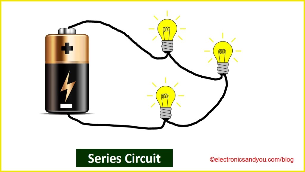
Web This Circuit And Circuit Diagram Contain A Cell And Two Lamps Connected In Series.
The cost to build a series circuit is less. Web difference between pictorial and schematic diagrams lucidchart blog. Web a circuit diagram, also known as an electrical diagram, elementary diagram, or electronic schematic, is a graphical representation that simplifies an electrical circuit.
Web A Circuit Diagram Is A Visual Representation Of An Electrical Circuit.
Series circuits are used in voltage divider circuits. The rc series circuit is shown in the figure below: What are series and parallel circuits electronics textbook.
Web Circuit Symbols And Circuit Diagrams.
Web when all the devices are connected using series connections, the circuit is referred to as a series circuit. Easy to design and build the circuit. Web question 1 draw connecting wires that will create a series circuit with all the components shown:
Web This Page Includes Details On The Series Circuit Diagram, Hints, And Frequently Asked Questions.
Symbol usage depends on the audience viewing the diagram. A series circuit consists of several resistances, connected one after the other in such a way that they form a chain (fig. Thus far, this unit of the physics classroom tutorial has focused on the key ingredients of an electric circuit and upon the concepts of electric potential difference, current and resistance.
Some Diagrams May Have Realistic Pictures To Make The Various Components Easier To Identify.
You just need to connect positive terminal of led with the one end of resistor and then connect another end of resistor with the positive terminal of battery. Web draw connecting wires that will create a series circuit with all the components shown: We'll go over all of the fundamental schematic symbols:
Web What Is A Pictorial Diagram?
We'll also go over a. Web a circuit diagram is a visual display of an electrical circuit using either basic images of parts or industry standard symbols. It does, however, show you the sequence in which the components are connected.
A Sinusoidal Voltage Is Applied And Current I Flows Through The Resistance (R) And The Capacitance (C) Of The Circuit.
Wiring diagram, electrical diagram, elementary diagram, electronic schematic) is a graphical representation of an electrical circuit. It acts as a current regulator. We produced this page to help those searching for a series circuit diagram, and ideally, you can resolve your problem with our info.
Web A Circuit Diagram (Or:
It serves as a visual tool for the design, construction, and maintenance. Pictorial diagrams can vary in level of detail. Series circuits schematic circuit diagrams there are many diffe ways to represent below is an artist s.
In A Series Circuit, Each Device Is Connected In A Manner Such That There Is Only One Pathway By Which Charge Can Traverse The External Circuit.
A pictorial circuit diagram uses simple images of components, while a schematic diagram shows the components and interconnections of the circuit using standardized symbolic representations. The advantages of series circuits include: A pictorial circuit diagram uses images of components (such as photos or sketches), while a schematic diagram shows the components and interconnections of the circuit using standardized symbols.
If A Component Breaks, The Current Flow Stops.

18 Best Series Parallel Switch Wiring Diagram

What is a Series Circuit? Advantages, Disadvantages and Examples
Parallel Circuit Definition Parallel Circuit Examples Electrical

PPT Series Circuits and Parallel Circuit PowerPoint Presentation

L2 Circuit Schematics Physical Computing

Series Parallel Circuit Series Parallel Circuit Examples Electrical
Electric Circuit Types Of Electric Circuit Industrial News News

Series circuit infographic diagram 3093702 Vector Art at Vecteezy
