Web servo motor controller circuit schematic. Dc servo motors can be controlled by using either the current of the field winding or the armature current.
DC Servo motor Theory, Circuit Diagram, Types, Characteristics
Servo Motor Diagram Circuit. Circuit diagram of ac servo motor. The diagram will also include the necessary wiring and connections between the components. How to build a servo motor circuit with arduino.
Using A Potentiometer Attached To The Rotating Shaft, Servos Sense Position.
In this tutorial, we will learn how to. Web servo motor driver circuit december 7, 2018 admin 3 comments here sub micro size servo motor is taken as a target device and we developed servo motor driver circuit for that motor. Servo motor (which needed to be tested) 555 timer ic;
Web An Introduction To The Concept Of Pulse Width Modulation.
Web definition of servo motor: Field controlled dc servo motors, armature controlled dc servo motors. The diagram will also include the necessary wiring and connections between the components.
The First Component Is The Driver, Which Is Responsible For Translating The Control Signal.
A servo testing circuit is shown in the above schematic diagram. Web circuit servo motors have three wires: How to control servo motors with arduino 3 examples.
An Equivalent Circuit Of Dc Servomotor Drive Scientific Diagram.
Dc servo motors can be controlled by using either the current of the field winding or the armature current. 33kω, 10kω (2peices), 68kω and 220ω resistors; Circuit diagram construction & working
Web The Servo Motor Drive Circuit Is A Critical Part Of The Motor's Operation.
The ground wire is typically black or brown and should be connected to a ground pin on the board. Web a servo motor is a combination of dc motor, position control system, gears. Web types of dc servo motor.
Hobby Servo Tutorial Servos Are Motors That Allow You To Accurately Control The Rotation Of The Output Shaft, Opening Up All Kinds Of Possibilities For Robotics And Other Projects.
Web a servo motor circuit diagram is a graphical representation of a servo motor's components. On the other side of the circuit, you will see the motor itself. Servo motors are widely used in different types of applications and suitable for movement or rotation based mechatronic needs.
Web A Servo Motor Circuit Diagram Provides The Clearest Insight Into How These Motors Work And How They Are Used In A Variety Of Applications.
Circuit diagram of ac servo motor. In the fields of winding and armature winding, these types of servo motors employs seperate dc sources. Short pins 2 and 6 (tr and th) and connect a 100nf capacitor between pin 6 and gnd and another 100nf capacitor between pin 5 (cv) and gnd.
Holding Position With A Servo.
Servo is a small device that incorporates a three wire dc motor, a gear train, a potentiometer,an integrated circuit, and an output shaft bearing (shown in figure). Stator of ac servo motor the stator of this motor which has a laminated structure, is wound with its two windings placed 90 electrical degrees apart in space. Web first, connect the pins 8 and 4 (vcc and rst) of the 555 timer ic to +5v supply and connect the pin 1 (gnd) to ground.
The Signal Pin Is Typically Yellow Or Orange And Should Be Connected To Pwm Pin.
As compared to large industrial electric motors, servo motors are not useful for continuous energy conversion. Accordingly, they are classified as: What is a servo motor ?
The Position Of The Shaft Of The Dc Motor Is Adjusted By The Control Electronics In The Servo, Based On The Duty Ratio Of The Pwm Signal The Signal Pin.
Web servo motor systems worksheet analog integrated circuits. A servo motor is a type of motor that can rotate with great precision. The 10kpot vr2, r1 and capacitor c1.
The Power Supply Is Usually Connected To The Mains Via A Plug, And Provides The Motor With A Continuous Supply Of Current.
Web published august 1, 2015 10 a apoorve author servo motor what is a servo motor? It is designed to allow users to quickly and easily identify all the individual parts, their roles, and how they all fit together. The circuit is designed to give control signals to the servo.ic1 is designed as an astable multi vibrator which can give pulses for the operation of the servo.
It Controls The Motor's Speed And Position By Converting Electrical Energy Into Mechanical Motion.
The great thing about a servo is it can be configured to hold its position between actuation steps. Web servo motor controller circuit schematic. How to build a servo motor circuit with arduino.
Web A Servo Motor Schematic Diagram Is Basically A Map Or Plan Of The Various Components And Connections Within A Servo Motor System.
Normally this type of motor consists of a control circuit that provides feedback on the current position of the motor shaft, this feedback allows the servo motors to rotate with great precision. Web as you will see in the servo circuit diagram below, the servo circuitry is built right inside the motor unit. At its heart, the drive circuit contains several components that work together.
This Article Will Explain What Servo Motors Are, How They Work, And Why They Are Important For Robotics Applications.
The holding torque provided by a servo motor is comparable to that from a stepper motor. It typically includes the power source, motor, control system, and feedback mechanism. Motors and selecting the right one learn all about different kinds of motors and how they operate.
The Power Wire Is Typically Red, And Should Be Connected To The 5V Pin On The Arduino Board.
Web block diagram showing how to drive a servo motor with a motor controller ic. It has a positionable shaft, usually fitted with gear and a control arm. Servo tester circuit diagram and working explanation.
Web In This Tutorial, We Will Learn How To Control A Standard Servo Motor, To Go Back And Forth Across 180 Degrees, Using A `For Loop ()`.
Construction of ac servo motor similar to a normal induction motor, this motor comprises of a stator and a rotor. Now, connect a 10kω resistor between pin 7 (dis) and +5v. Web circuit components +9v to +12v power supply;
Web Pcb Block Diagram:
It’s very similar to a standard dc motor. Web schematic diagram and operation analysis of the circuit. A tiny dc motor, feedback potentiometer, gearbox, motor drive circuit, and feedback control loop are all parts of a dc servo motor.

Arduino Servo Motor Control Using Potentiometer Push Button

How to Interface Servo motors with Arduino Homemade Circuit Projects

Interfacing Servo Motor with AVR Microcontroller Atmega16

Servo Motor Controller and Tester Circuit Using 555 IC

How to Control Servo Motors with Arduino (3 Examples)
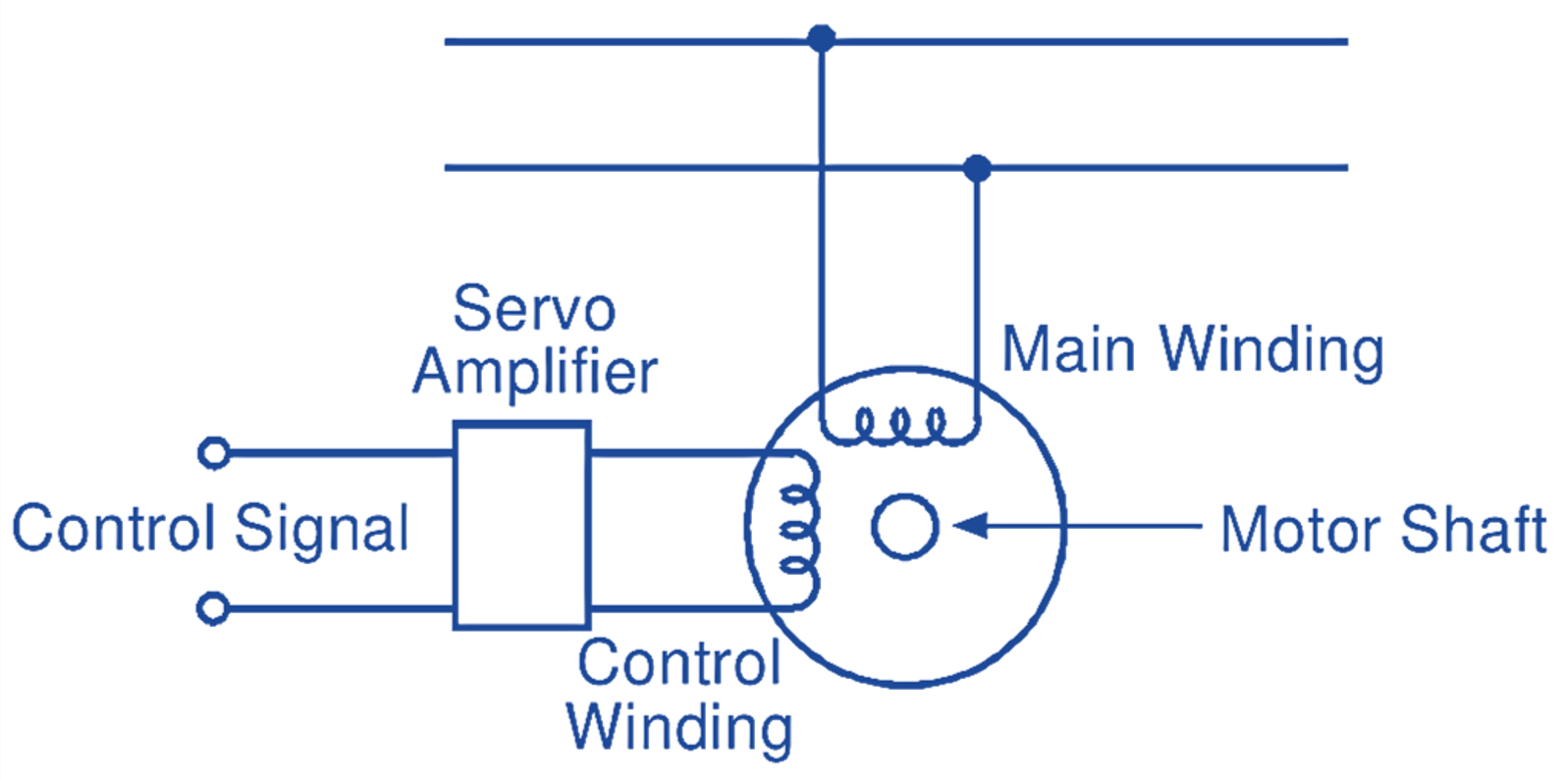
AC Servo motor Working Principle, Circuit Diagram, Construction

How can I improve this circuit to drive a servo with a 555 timer

DC Servo motor Theory, Circuit Diagram, Types, Characteristics
